 EN
EN



DMX512 Basics: How Stage Lighting Controllers Work
A stage-lighting system may include moving heads, LED PARs, strobes, dimmers, and effects fixtures, but the system needs one shared language before those units can perform as a show. That language is DMX512. A DMX 512 controller is the device that places those instructions onto the control line. A DMX 512 controller turns an operator’s fader moves, buttons, cues, and stored scenes into a stream of control values that fixtures can understand.
For a venue technician, rental team, or first-time system planner, the useful question is not simply “What does DMX mean?” It is: how does a controller send a command through the line, how does each fixture know which command belongs to it, and what must be checked before a show? This article follows that signal path from controller to fixture.
What a DMX 512 Controller Does
A DMX 512 controller is the command source in a DMX lighting system. It repeatedly sends a set of numerical values down a DMX cable. Each value occupies a channel, and the receiving fixtures translate their assigned channel values into actions such as dimmer level, color mix, pan, tilt, gobo selection, shutter, or an internal effect.
For a DMX 512 controller, the “512” describes the maximum number of usable control slots available in one DMX universe. The physical layer uses differential EIA-485, commonly called RS-485, signaling. In practical terms, a single controller output can continually refresh many separate lighting parameters over one daisy-chained control line. A controller does not provide fixture power; it provides the instructions.
Small hardware controllers often give operators faders for direct channel control, buttons for selecting fixtures, and memory banks for scenes or chases. Larger consoles and software systems use the same DMX concept while adding cue stacks, fixture libraries, visualizers, and networked outputs.
Follow the Signal: Controller, Cable, Fixture, and Terminator
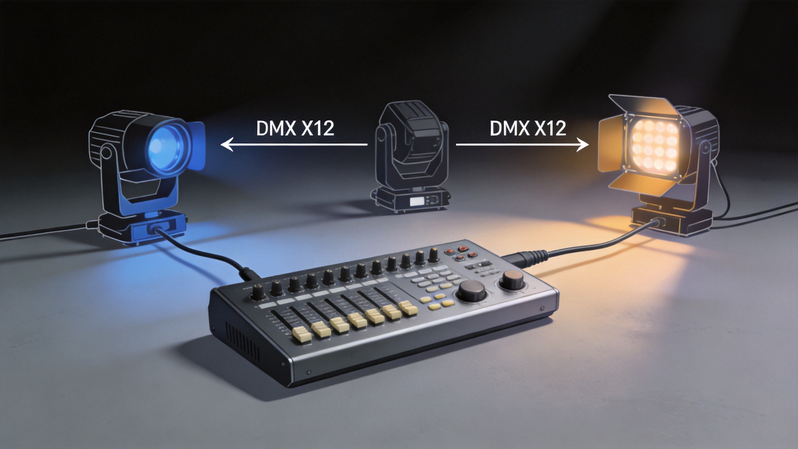
For any DMX 512 controller, the simplest working chain is straightforward:
- The DMX 512 controller creates a data packet containing channel values.
- A DMX cable carries the signal from the controller’s output to the first fixture’s DMX input.
- The signal is passed from that fixture’s DMX output to the next fixture, creating a daisy chain.
- Each fixture listens only to the address range assigned to it.
- A terminator at the end of a long or noise-prone line can help reduce signal reflections.
This arrangement explains a common beginner mistake: a fixture can be powered and still remain unresponsive if the data line, address, mode, or controller patch is wrong. Power makes the light available; DMX tells it what to do.
It is also important to distinguish a controller from a decoder. A controller originates the lighting instructions. A DMX decoder receives those instructions and converts them for compatible LED equipment or drivers. In a conventional stage fixture, the fixture’s electronics usually perform the interpretation internally.
Channels, Fixture Modes, and DMX Addresses
Every controllable function uses one or more channels that the DMX 512 controller can refresh continuously. In a simple RGB fixture, three channels may control red, green, and blue. A moving-head fixture can need many more because it may expose separate channels for pan, tilt, fine movement, dimmer, shutter, color, gobo, focus, prism, reset, and macros.
Before assigning addresses on the DMX 512 controller, choose the desired fixture mode. A compact mode may offer fewer functions and use fewer channels. An extended mode may provide finer control but consumes a larger block of a universe. The manual for the selected fixture mode tells you how many channels that fixture needs.
The DMX address is the first channel a fixture listens to. For example, if Fixture 1 uses 8 channels and starts at address 1, it uses channels 1 through 8. A second 8-channel fixture can start at address 9 and use channels 9 through 16. This prevents the fixtures from reacting to the same values unintentionally.
| Fixture | Selected mode | Channels used | Start address | Channel range |
|---|---|---|---|---|
| LED PAR 1 | RGBW | 4 | 1 | 1–4 |
| LED PAR 2 | RGBW | 4 | 5 | 5–8 |
| Moving head | Extended | 16 | 9 | 9–24 |
Two fixtures may deliberately share an address when they are intentionally configured to behave identically. Otherwise, unique address blocks provide independent control and make troubleshooting much easier.
How Operators Turn Channel Values into a Show
Once fixtures are connected, set to DMX mode, and addressed, the DMX 512 controller can control them one channel at a time or as grouped fixtures. An operator may raise a dimmer channel, fade color channels, move a fixture to a position, then save that state as a scene. Several scenes can be arranged into a chase or recalled as show cues.
For an awareness-stage setup, start with a basic goal: make every fixture respond predictably. First test the dimmer or shutter channel, then color, then movement and effects. This reveals whether the controller’s fixture profile and the fixture’s actual channel mode match. If a fader moves a gobo when you expected a dimmer, the patch or mode needs review rather than more programming.
For systems that need a physical control surface, a 1024 DMX lighting Controller can be considered as a product-category reference while you confirm the fixture count, channel demand, and operating workflow. Confirm the product documentation and the fixture manuals before final system design.
A Practical DMX512 Setup Checklist
- Match the control mode: Set every fixture to DMX mode, not sound-active, auto-run, or master/slave mode.
- Document addresses: Write down the fixture name, selected mode, channel count, start address, and physical location.
- Use a true data path: Build a controller-to-fixture daisy chain instead of treating DMX like an audio splitter network.
- Check direction: Connect controller output to the first fixture input, then continue from output to input.
- Plan capacity: Add the channels used by all fixtures. If the total exceeds 512, plan another universe and compatible distribution or networking hardware.
- Terminate when appropriate: At the end of a longer line, use a suitable terminator according to the equipment guidance.
- Test before programming: Verify one fixture at a time before building complicated looks, scenes, or chases.
Common Problems and What They Usually Mean
The fixture does not respond
Check power, DMX mode, start address, cable direction, and whether the controller has selected the intended fixture or channel page. A known-good fixture and a short cable are useful for isolating the problem.
Several fixtures respond together
They may have the same start address, or they may be intentionally patched as a group. Review the address worksheet and the selected fixture mode.
Controls affect the wrong function
On a DMX 512 controller, this usually points to a mode mismatch. The controller may be patched for a 16-channel profile while the fixture is set to a 12-channel profile, so every function appears shifted.
The last fixture behaves erratically
Inspect cable quality, connector wiring, chain length, and the end-of-line termination approach. Also remove unnecessary adapters while testing.
Why DMX512 Still Matters in Stage Lighting
DMX512 remains useful because a DMX 512 controller makes a mixed rig manageable: an operator can coordinate dimmers, color fixtures, moving heads, and effects from a central control point. The protocol itself is only the transport; the real value comes from disciplined addressing, correct fixture modes, clear documentation, and rehearsal.
Start by mapping the signal path and channel plan before building cues. When the DMX 512 controller, fixture modes, addresses, and cable chain agree, even a modest stage-lighting system becomes easier to operate, troubleshoot, and expand.